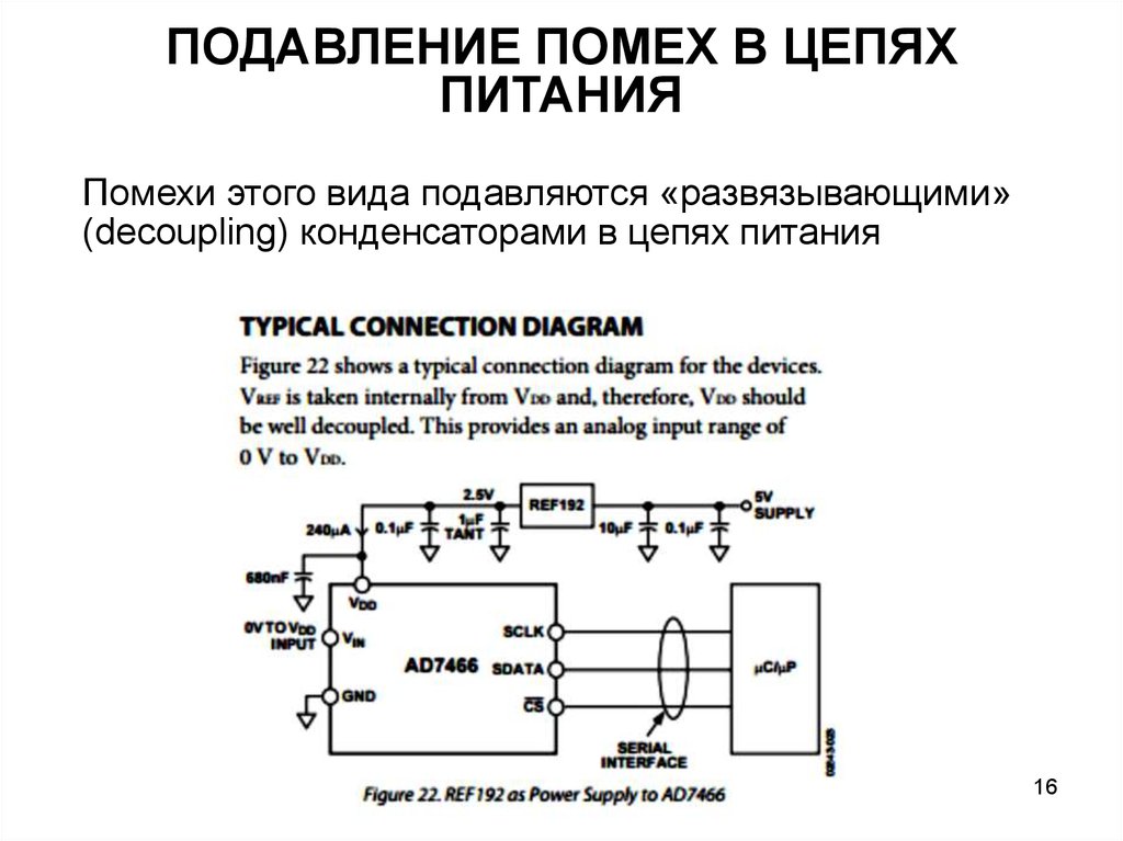
Что такое фазовый подавитель помех. Как он работает. Какие преимущества дает использование фазового подавителя помех. Как правильно настроить и использовать фазовый подавитель помех. Какие модели фазовых подавителей помех существуют на рынке.
Что такое фазовый подавитель помех и как он работает
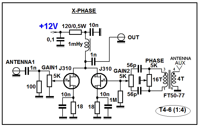
Фазовый подавитель помех (QRM Eliminator) — это устройство, которое позволяет значительно снизить уровень помех при приеме радиосигналов. Принцип его работы основан на подавлении нежелательных сигналов путем сложения их с сигналами противоположной фазы.
Как это работает? Фазовый подавитель имеет два входа для подключения антенн:
- Основная приемная антенна
- Вспомогательная антенна для приема помех
Сигналы с обеих антенн поступают в устройство, где происходит регулировка их амплитуды и фазы. Затем сигналы складываются, в результате чего помехи компенсируются, а полезный сигнал усиливается.
Преимущества использования фазового подавителя помех
Использование фазового подавителя помех дает радиолюбителям ряд существенных преимуществ:
- Значительное снижение уровня атмосферных и индустриальных помех
- Возможность приема слабых сигналов на фоне сильных помех
- Улучшение разборчивости речи и телеграфных сигналов
- Снижение утомляемости оператора при длительной работе
- Возможность работы в условиях сильных помех в городской среде
По отзывам радиолюбителей, использование фазового подавителя помех позволяет снизить уровень QRM на 10-20 дБ и более. Это дает возможность уверенно принимать корреспондентов, которые ранее были неразличимы на фоне помех.
Как правильно настроить фазовый подавитель помех
Для эффективной работы фазового подавителя помех крайне важна его правильная настройка. Основные этапы настройки:
- Подключите основную приемную антенну к первому входу устройства
- Подключите вспомогательную антенну для приема помех ко второму входу
- Настройтесь на частоту с сильной помехой
- Регулируя амплитуду и фазу сигнала от вспомогательной антенны, добейтесь максимального подавления помехи
- Проверьте работу на разных диапазонах и при необходимости подстройте
Важно помнить, что настройки могут меняться при смене диапазона или появлении новых источников помех. Поэтому периодически нужно проверять и корректировать настройки фазового подавителя.

Выбор вспомогательной антенны для фазового подавителя
Правильный выбор вспомогательной антенны очень важен для эффективной работы фазового подавителя помех. Какие антенны лучше использовать?
- Короткий штырь длиной 1-2 метра
- Рамочная антенна небольшого диаметра
- Активная антенна с малошумящим усилителем
Вспомогательная антенна должна эффективно принимать помехи, но при этом слабо реагировать на полезные сигналы. Ее располагают перпендикулярно основной антенне на расстоянии 3-10 метров.
Эксперименты с разными типами вспомогательных антенн позволят подобрать оптимальный вариант для конкретных условий приема.
Популярные модели фазовых подавителей помех
На рынке представлено несколько моделей фазовых подавителей помех от разных производителей. Рассмотрим наиболее популярные устройства:
MFJ-1026
Классическая модель от американской компании MFJ Enterprises. Основные характеристики:
- Диапазон частот: 1.8-54 МГц
- Подавление помех: до 50 дБ
- Регулировка фазы и усиления
- Встроенный предусилитель
- Цена: около $200
ANC-4 от Timewave Technology
Компактное устройство с автоматической настройкой:

- Диапазон частот: 0.3-80 МГц
- Автоматическая подстройка фазы и усиления
- Подавление помех: до 40 дБ
- Малые размеры
- Цена: около $300
QRM Eliminator от RA0SMS
Отечественная разработка с широкими возможностями:
- Диапазон частот: 0.1-150 МГц
- Цифровая обработка сигналов
- Запоминание настроек для разных диапазонов
- Подавление помех: до 60 дБ
- Цена: около 15000 руб
Самодельные конструкции фазовых подавителей помех
Для радиолюбителей, увлекающихся конструированием, существует возможность изготовить фазовый подавитель помех своими руками. Какие преимущества дает самостоятельная постройка устройства?
- Значительная экономия средств
- Возможность адаптации под конкретные условия приема
- Получение опыта и углубление знаний
- Удовлетворение от работы на самодельной аппаратуре
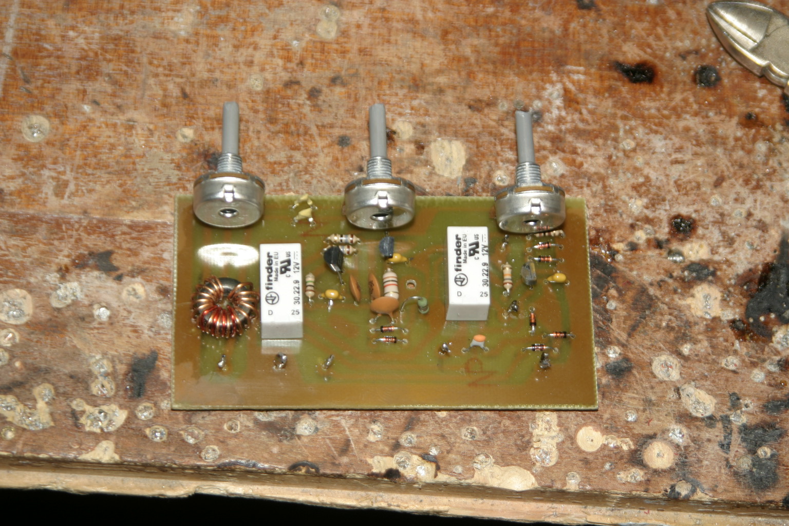
В интернете можно найти множество схем и описаний самодельных фазовых подавителей помех различной сложности. Наиболее простые конструкции содержат фазовращатель на основе RC-цепочки и регулируемый усилитель. Более сложные варианты используют цифровую обработку сигналов на микроконтроллерах.

Альтернативные методы борьбы с помехами
Фазовый подавитель помех — эффективное, но не единственное средство борьбы с QRM. Какие еще методы могут использовать радиолюбители для улучшения приема?
- Установка антенны подальше от источников помех
- Использование направленных антенн
- Применение режекторных фильтров
- Экранирование и заземление аппаратуры
- Использование цифровой обработки сигналов (DSP)
Комплексное применение различных методов позволяет добиться наилучших результатов в борьбе с помехами. Фазовый подавитель при этом может стать важным элементом общей системы подавления QRM.
Заключение: стоит ли использовать фазовый подавитель помех
Подводя итог, можно сделать вывод, что использование фазового подавителя помех дает радиолюбителям существенные преимущества:
- Значительное улучшение качества приема в условиях сильных помех
- Возможность работы со слабыми сигналами
- Снижение утомляемости при длительной работе в эфире
При этом важно помнить, что фазовый подавитель — не панацея, а лишь один из инструментов в арсенале радиолюбителя. Для достижения наилучших результатов его нужно правильно настроить и использовать в комплексе с другими методами борьбы с помехами.
Стоит ли приобретать или изготавливать фазовый подавитель помех? Если вы часто сталкиваетесь с проблемой сильных помех при приеме, то однозначно стоит. Это устройство позволит вам существенно повысить эффективность работы в эфире и получить больше удовольствия от любимого хобби.
Does a (resonnant) EFHW reduce urban noise? — Antennas
ON4KJM
#1
I am currently using an end-fed wire of about 23 m. The KX3 ATU achieves a “reasonable” tune on it with the help of a 1:4 balun and a random counterpoise. It radiates something useful as can be seen with RBN.
But the noise level on receive is very high. Around S9 on all bands. It makes SOTA chasing virtually impossible as I am so to speak deaf.
I wonder if going through the trouble of building a 1:49 unum and tuning the wire to a 40m EFHW would reduce the receive noise.
Opinions? ideas?
73 de ON4KJM
KT5X
#2
Probably not. What might help is a simple choke balun. Put it at the radio end of your feedline.
73 Fred kt5x
1 Like
2E0AGB
#3
Jean I have an EFHW with a 49:1 unun and I still get the same noise level as yourself even with a line isolator in place it makes no difference and I have noticed that it starts at the same time each morning so it may be down to british telecom as we call it here.
Best 73 Allen
1 Like
G3CWI
#4
No it doesn’t.
G4IPB
#5
This Clean Up Your Shack – 2019 | GM3SEK’s Technical Blog might be of some help as it is likely that some of the noise is entering in other ways.
OH7BF
#6
S9 on all bands is pretty high level of QRM. Maybe some local strong RFI gets into receiver. This can be tested with radio internal attenuator or with external stepped attenuator like Elecraft AT1.
Some commercial solutions
Palomar Engineers®Generic Transceiver RFI Kits — Transceiver RFI Kits — Palomar Engineers®
Generic Transceiver RFI Kits — Transceiver RFI Kits — Palomar Engineers®
Est. reading time: 1 minute
Balun like Elecract BL2 or choke balun from DX wire at antenna feed point helps to reduce RFI fed back from receiver system to the antenna as pointed out by others already.
73, Jaakko ac1bb/oh7bf
VK1DA
#7
Assuming you have eliminated all possible noise sources in your own house, by switching everything off, the next thing is to ensure that the feed-in system is not capable of picking up noise itself and bringing it to the radio. Run the radio on battery power temporarily to eliminate the power supply.
If your antenna is partly vertical and low to the ground, to connect to your balun and the random counterpoise, it seems likely that the lower sections of the antenna are exposed to noise generated within your own house, as well as the neighbours’ houses.
Is the counterpoise really a counterpoise, lying on the ground to couple to real ground capacitively? If it’s in the air, it just part of the antenna, which is in that case, an Off Centre Fed antenna.
Hope this is food for thought and experimentation.
73 Andrew VK1DA/VK2UH
1 Like
K7WXW
#8
I feel your pain. I live in an urban environment, surrounded by solar panel installations, switch mode power supplies running electronics and houses with grow lights. My baseline noise level is S7 and that’s after cleaning up all the noise sources in my home (lots of ferrite, using linear power supplies, eliminating LED lights, etc). If I really want to spend a day chasing, I end up working portable…
That said, the first thing I would do if I were you is go someplace RF quiet and check the baseline noise level of your system. You should be sure that your base system noise level is acceptable. The second thing I would do is clear out all the RF noise you are generating in your home. Track down the work done by K9YC for a good primer on this or the ARRL book on RFI. The third thing I would do is understand the limits of chokes, especially when applied to unbalanced antennas like endfeds or any antenna that is intended to be multi-band so you have a realistic idea about what kind of improvement is possible.
Good luck! 73 Bill K7WXW
VK3AFW
#9
As Richard said changing the method of feed for an end fed antenna doesn’t change its noise pick up.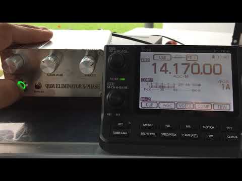 The antenna can’t change the environment. The advice Andrew gives in locating noise sources you own is good. Locating and doing something about other noise sources is a whole new subject.
My experience supports the idea that a balanced doublet with balanced feed picks up less noise than end fed or vertical types.
Many VKs retire to the countryside just to escape the noise. Being a regular SOTA activator also helps. If you are a member of a Club perhaps you can organise a remote station in a quiet place. Several VKs have put a lot of effort into setting up a remote station on a hill with beams from 20 m to 2 m. They work extraordinary DX.
Check out VK3MO and VK3OE/R.
My noise level used to be from S6 down to S2 for 80 m to 10 m. Now it is S9 all the way through. Broadband internet?
Life isn’t always easy.
73
Ron
VK3AFW.
G8ADD
#10
ON4KJM:
I wonder if going through the trouble of building a 1:49 unum and tuning the wire to a 40m EFHW would reduce the receive noise.
No, it won’t, I’ve tried it myself. The only success that I got was to set up a vertical as far away from the house as possible. Verticals are notoriously noisy but this one was about four S-points quieter than the main antenna which is a doublet fed with window line, and that was a couple of S-points quieter than an antenna in the roof space. Modern houses are full of noise makers, if you cure all yours you still get noise from the neighbours. MFJ sell a unit that will null out a noise source but will not cope with more than one source.
We’re all doomed!
G4IPB
#11
…nearly doomed… We have a “proper” fibre — the glass variety not what most providers describe as fibre when what they mean is a pair of copper wires… That still leaves about 400 billion switched mode power supplies (and that is just the ones used by my children), a neghbours solar panels and the one remaining neigbour who has stayed on ADSL, and something — yet to be identified which pops up occasionally accross all of HF- might be the ADSL… so there is hope but it involves a digger and lots of optical fibre.
PS In a twist of irony the noisiest power supply now covered in ferrites is the one for the fibre modem supplied by … BT… 73 Paul
EI6FR
#12
As nobody’s mentioned it . Have you looked at installing a Delta or Quad loop antenna ? The closed loop antenna picks up considerably less noise in an urban environment than a vertical or other horizontal wire antenna in my experience.
Declan
ei6fr
F5JKK
#13
Hi Jean-Marc, @ON4KJM
I have some QRM here too after 17z and using this QRM Eliminator :
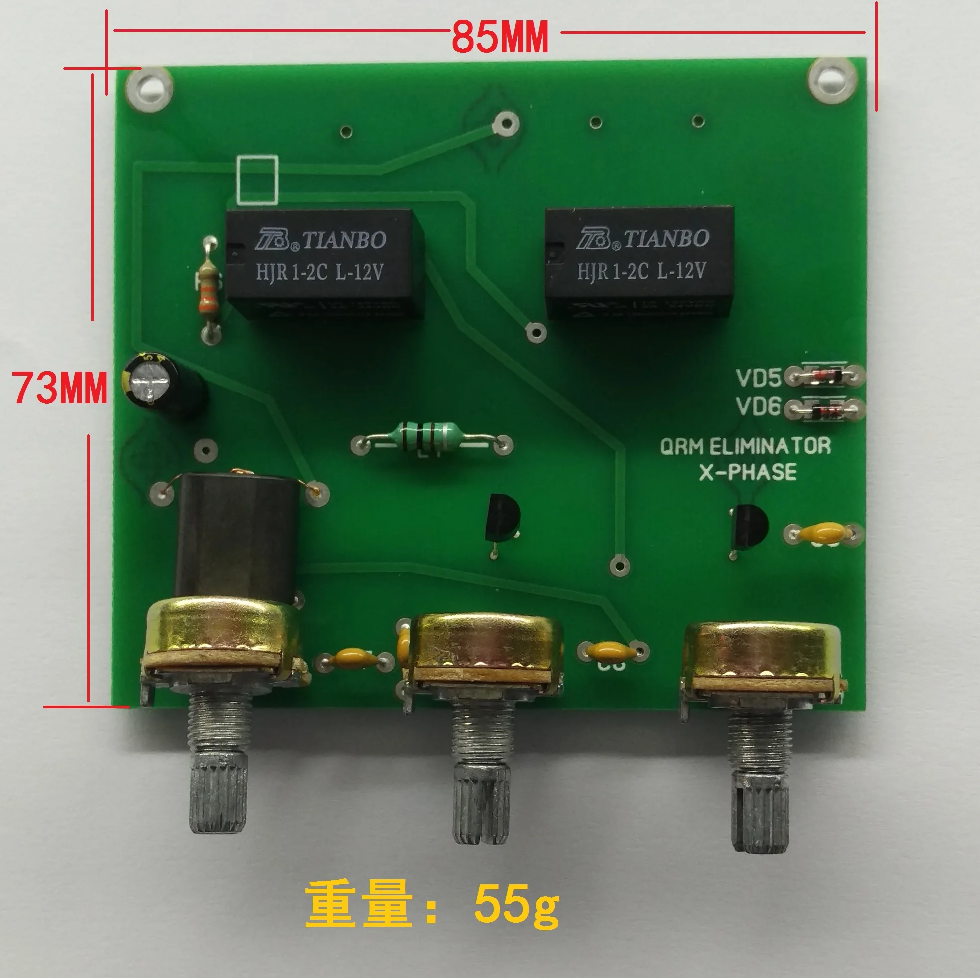
QRM Eliminator X-Phase (Фазовый подавитель помех) Update 09 Apr 2019
Hamradio, stm32, esp8266, разработка электроники, микроконтроллеры, встраиваемые системы
Working for me
73 Éric
ON4KJM
#14
Thank you all for pointing me in the right direction. The noise is coming from the shack. First source is the power supply : when I disconnect it (and listen on the internal batteries), the noise drops 1 s point. A clip-on ferrit didn’t help. As I have a lot of computer related stuff (for work) that can be part of the problem. I think it is an up-hill battle.
I will see what I can do but I think that I will continue to focus on being radio-active in the outdoors.
73 de ON4KJM
1 Like
Best mutliband antenna for chasing — Equipment
SOTA ReflectorNZ4R
#1
My home-made fan dipole up 40’ does well … except for receiving QRP. So I have been shopping products and designs for a Multiband antenna for my home for chasing. I would value the comments and experience of my fellow chasers and activators. What have you had success with and what would you avoid? I use my KX3 at home with 100w amp. Our house is on a hillside in the mountains of NC with rocky soil. Thanks to all! Scott kw4jm
VE6VID
#2
If you can afford it, a multi band yagi of sorts. That will increase things for you. Even a 2 element homebrew pointed in your normal direction.
Malen
VE6VID
VK2HRX
#3
I use a 40m loop
DD5LP
#4
Another vote here for the 40m horizontal full wave loop (aka Sky-loop). Cheap to make very low noise omni-directional on 40m, some gain on higher bands. Works on 40,20,10m without a tuner and the WARC and 15m band with one. (possibly also 6m but I have a beam for 6/4/2m).
Downside is you need space to put it up — ideally you don’t want it going over the house roof if possible.
73 Ed.
DD5LP / G8GLM / VK2JI blog – 29 Aug 1640 metre Horizontal Loop Antenna.
The 40m Loop antenna Ed, VK2JI (This antenna is also known under the names “Sky Loop” and “DX-Buster” and is very similar to a horizontal delta loop). The following is an a…
Or if you want to buy rather than build Scott (remembering you will still need to supply supporting masts) there’s this commercial product:
http://chameleonantenna.com/WIRE_ANTENNAS/CHA_SKYLOOP/CHA_SKYLOOP.html
VK3AFW
#5
Hi Scott,
Your fan dipole is probably as good as it gets unless you have lots of space, significant finance and can put up a decent antenna farm.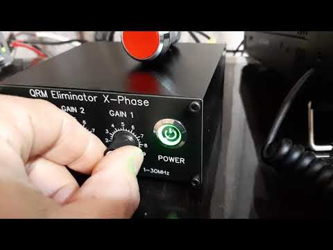 You don’t say what frequencies you are interested in.
I used to run a TH6 beam on 20/15/10 and it was very good even at a mere 40 ft. You can buy multiband HF beams with 3 to 6 active elements and they will outperform a simple dipole at the same height. Higher is better. The biggest ears have stacked yagis on 200 ft towers.
For 30 m, 40 m and 80 m you can get monoband beams but you will need a stronger tower for these. Probably best not to have more than 2 big beams per tower and make sure the system can handle the wind loads.
You could, if you have big acreage, put up 6 big Rhombics to give virtual 360 degree gain but again they need to be at 100 ft or so to work properly.
Expensive? You betcha. We all make the mistake of spending more on the rig than the antenna.
If the other guy is QRP on a peak best to first get a quiet QTH out of town. Put up the biggest antenna system the bank can buy for you. Operate a remote station.
Even a humongous antenna may not give much improvement in received S/N if your QRH is in the middle of suburban RF QRM hell.
My own set up is modest and I accept that I can’t work many activators because they are in the noise.
Good luck
73
Ron
VK3AFW
G8ADD
#6
The antenna that works for me is a G5RV set up as a doublet, tuned with an MFJ-949E versa tuner. This enables me to get 1:1 SWR on all bands 160 metres to 6 metres, and I chase successfully on all those bands except for 10 MHz (I don’t do CW at present.) My limiting factor is urban noise, which comes at me from all azimuths.
The only advantage a doublet has over a fan dipole is that a fan dipole for eleven bands might be a bit of a beast to set up, but the doublet does it with one wire. An antenna with gain will be better than a simple wire antenna but will be limited to one or a few bands.
Another possibility is two phased verticals that will enable you to switch the directions of the major lobes and give some gain.
S52CU
#7
Another vote for horizontal loop antenna. Mine is a little shorter than 40 m wave lenght (space restriction, one leg over the house roof). It is made of 38 m long wire, 7 m agl and fed by 300 ohm twin lead cable, followed by a 1:4 balun and 2 m RG58 coax cable into my KX3. It is usable on all bands from 40m to 6m, KX3 can easely tune on all these bands. Not great DX antenna, but I have some DX activators and other stations from NA, SA, Australia etc in my log. It is very simple to build and it is worth trying if you have enough space.
Good luck with your new antenna,
73,
Mirko
1 Like
OE6FEG
#8
I actually use the same type of antenna for chasing as I do for activating:
There seems to be a lot of interest in antennas that can be used with an internal ATU, such as that found in the KX3/2/1, so I thought I would share a rather clever design that was given to me by G3UNA, who in turn got it from M0RZF: http://www.m0rzf.co.uk/styled/ It is generally called an End Connected Windom or ECOCFD. The name says ‘end connected’ and not ‘end fed’ for a good reason. It offers almost all the advantages of an EFHW antenna (resonance and no long coax feeder to carry), whilst …
It works well on all bands (WARC bands too when they are open). It is extremely simple to build and it connects at the end, thus offering all the benefits of a resonant end fed wire, minus about 4000 ohms impedance. Whilst I do not hear every SOTA op at home, when the bands are open I have worked plenty of DX with only 15w, so I have no complaints.
73 de OE6FEG / M0FEU
Matt
N1EU
#9
IMHO you’ll be wasting your time trying to improve the fan dipole unless you can put up a yagi.
Barry N1EU
2 Likes
AC7P
#10
When chasing, hearing the activators is also my weak link.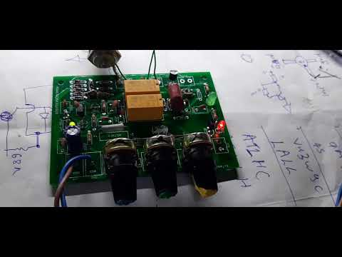 I know that many other chasers are hearing much better than I. Due deed restrictions, the best I can do for a home antenna is a 40 meter inverted vee with apex at 35 feet and antenna tuner that allows me to work all HF bands. But I have found that my real problem is the local noise in my rocky one-acre Texas Hill Country suburban lot. I purchased a Timewave ANC-4 noise canceler which is inserted between the antenna tuner and transceiver and it has greatly helped with receiving. It uses a small antenna to sense the noise and a phasing system to remove it from the received signal. It does not perform this perfectly and it takes some tinkering with the noise antenna and how to use the device. But, I know that without it I would not be able to hear many of the activators that i do now.
73, Don AC7P
MM0FMF
#11
AC7P:
It uses a small antenna to sense the noise and a phasing system to remove it from the received signal
This! Remove as much noise as possible before the RXer not with DSP filters after the weak signal has already been masked.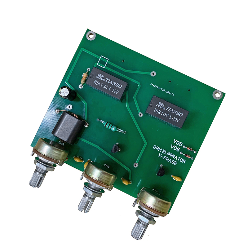
G8ADD
#12
MM0FMF:
This! Remove as much noise as possible before the RXer not with DSP filters after the weak signal has already been masked.
I might be wrong but I think that this is a council of perfection which falls down if you suffer from multiple noise sources.
MM0FMF
#13
sigh
K6WRU
#14
Multiple noise sources add linearly, so that isn’t a problem.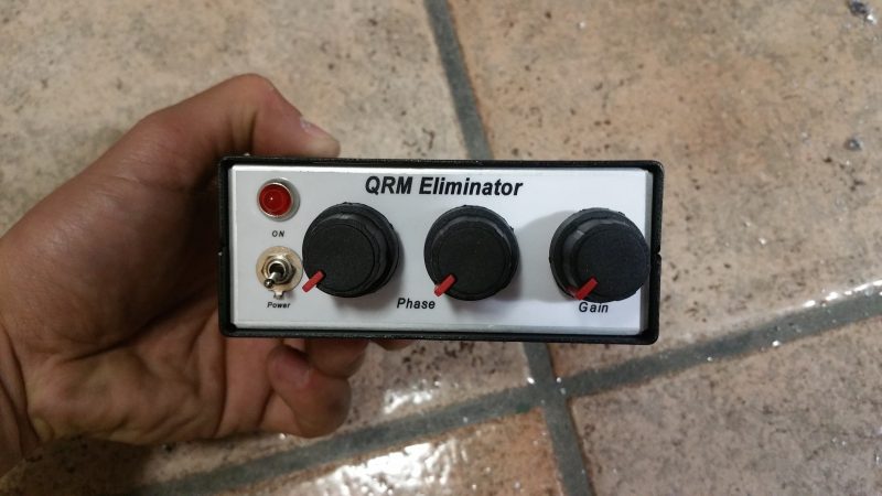
The position of the noise sampling antenna relative to the receive antenna can change the effectiveness. Changing position or changing frequency might require retuning the noise cancelling network. Nulling moving or changing noise sources will also need occasional retweaks.
wunder
DD5LP
#15
AC7P:
I purchased a Timewave ANC-4 noise canceler which is inserted between the antenna tuner and transceiver
I have a European equivalent from RA0SMS (based on a German design I think) and now that I have two antennas up, I must get around to testing it!
ra0sms.ruQRM Eliminator X-Phase (Фазовый подавитель помех) Update 09 Apr 2019
Hamradio, stm32, esp8266, разработка электроники, микроконтроллеры, встраиваемые системы
https://www. eham.net/reviews/detail/13511
Not something applicable to activating but I’m hoping it’ll help during chasing. Switching between the antennas I can hear a station weakly on the loop but not on the end-fed, so if the X-phasing logic works, it ought to be possible to get rid of the common noise that is on both antennas leaving hopefully a clearer signal from the weak station.
Don, can you tell me — do you have to re-adjust the unit if you move a few kHz within a band or can it be set on one band and used there just by switching it in?
73 Ed.
AC7P
#16
Ed — The Timewave unit does not require much adjustment with frequency changes. What i have found is that it is quite broad. Typically, I “adjust” the unit on 14 MHz and the same setting works just fine also for 18 MHz and 10 MHz.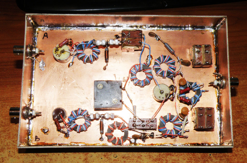 The “adjustment” involves starting with the unit off and noting the noise level on the S meter. Then turn the unit on (which inserts a loss) and increase the noise antenna gain until the original S meter reading is reattained. Then adjust the phasing for a null in the noise. For some reason (probably related to K6WRU’s comment) the unit does not work well on 7 MHz. There, the adjustments become overly sensitive and I typically find I have better performance with the unit off.
As for the MM0FMF and G8ADD comments, I knew when I posted my initial response that I was going to touch some nerves. I recall the subject of phasing system noise removal was discussed before. But it seemed there was no consensus if this was a worthwhile approach. Theory aside, the Timewave unit works for me and with the currently poor propagation conditions I would not be chasing SOTAs at all without it.
Don AC7P
MM0FMF
#17
AC7P:
I would not be chasing SOTAs at all without it.

This! That’s why I think these units are worth trying out.
N2ESE
#18
WOW ! , After reading all the comments, I just bought one from HRO!
$ 189.00 and free shipping!
73 Gary N2ESE
DD5LP
#19
AC7P:
Timewave unit works for me and with the currently poor propagation conditions I would not be chasing SOTAs at all without it.
Good on yer Don — and thanks for your comments, it might just stir me up to try my unit out at last!
73 Ed.
G4OBK
#20
Radio Amateurs should not be buying wire antennae. They are easy to make yourself and cheap.
The question from KW4JM was about an antenna and not aids to reduce noise, so going off topic!!
For chasing a good all round antenna is an Off Centre Fed Dipole — known by some as a Carolina Windom. Has worked well for me ovet the last 18 months when I have not had an HF beam — problem soon to be remedied, so expect bigger signals from G4OBK on 20m and up soon.
I have used the 80m version since Jan 1st 2017. 80m length OCFD top into a 4:1 balun > 20 feet drop coax > to a choke balun and then RG-213 back to the shack. It just happens to fit into my back garden as the 80m version. A half sized 40m version should be used if you do not have the space.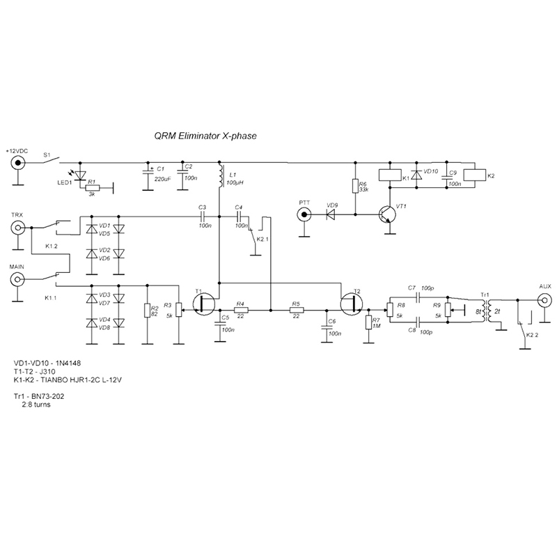 Look at the Chaser database. it works for me. Fixed into a beech tree 40 feet AGL at most. the short side is at 45 degrees, but it still works out fine business. The long side is almost horizontal at 40 feet from the beech tree to my house gable end.
From experience this is a better all round performer than the (obsolete in my opinion) G5RV.
If you want significant gain you are talking about a mast to support the aerial, for HF you probably need to buy need a multiband yagi, quad or Hexbeam type of antenna, a rotator and more engineering work. That opens up a whole new can of worms… Have you got the money, time and interest to facilitate that I wonder?
73 Phil
1 Like
next page →
Other SOTA sites: SOTAwatch | SOTA Home | Database | Summits | Photos | Shop | Mapping | Sotlas | FAQs | Contact SOTA
A 10 ГГц цифрового фазового шумового фильтра с 14 дБ -подавлением шума и чувствительностью к шуму -127 дБК/Гц при смещении 1 МГц
- doi: 10.
 1109/rfic.2018.8428979
 - ID Corpus: 51980816
 @Artcle @Artcle @Artcle @Artcleclecle @Artclecle @Artcleclecle @Artcleclecle @Artcleclecle @Artclecle @Artcleclecle @Artcleclecle @Artcleclecle @Artclecle.
  title={Цифровой фильтр фазового шума 10 ГГц с шумоподавлением 14 дБ и чувствительностью к шуму −127 дБн/Гц при смещении 1 МГц},
  автор = {Туннин Ху, Шилей Хао и Цюнь Джейн Гу},
  Journal={2018 симпозиум IEEE по радиочастотным интегральным схемам (RFIC)},
  год = {2018},
  страницы = {48-51}
} - T. Hu, Shilei Hao, Q. Gu
- Опубликовано 1 июня 2018 г.
- Physics
- Симпозиум IEEE по радиочастотным интегральным схемам (RFIC) 2018 г.
В этой статье мы представляем цифровой фильтр фазового шума частотный дискриминатор на основе временного усилителя (TA-TDC). TA-TDC повышает чувствительность системы и подавляет флуктуации предельного цикла, которые ограничивают работу квантованных систем. При смещении 1 МГц он демонстрирует подавление фазового шума на 14 дБ с чувствительностью −127 дБн/Гц для тактовой частоты 10 ГГц. Интегральный джиттер в полосе частот от 10 кГц до 100 МГц составляет 81 фс. Диапазон смещения частоты подавления фазового шума составляет от 40 кГц до…
См. на IEEE
doi.org
ПОКАЗАНЫ 1-8 ИЗ 8 ССЫЛОК
КМОП-фильтр фазового шума с пассивной линией задержки и частотным дискриминатором на основе PD/CP
- Shilei Q, T. Hulei Hao, T. Gu
-
Physics, Engineering
IEEE Transactions on Microwave Theory and Techniques
- 2017
КМОП-фильтр фазового шума (PNF), активируемый пассивной линией задержки (DL) и фазовым детектором/накачкой заряда (PD/CP). ) предложен частотный дискриминатор. Контур с задержкой и смещение постоянного тока…
90-нм CMOS 5-ГГц кольцевой генератор ФАПЧ с активным подавлением фазового шума на основе распознавателя задержки
Аналоговая адаптивная архитектура подавления фазового шума с прямой связью, которая извлекает и подавляет фазовый шум RO за пределами полосы пропускания PLL вводится, который может улучшить фазовый шум при произвольной частоте смещения и полосе пропускания и нечувствителен к изменениям процесса, напряжения и температуры.
Дискриминатор частоты/фазы FBAR/CMOS и система подавления фазового шума
В статье представлена схема подавления фазового шума с использованием чувствительного малошумящего фазочастотного дискриминатора на основе резонатора. В дискриминаторе используется объемная тонкая пленка с высоким коэффициентом качества…
90-нм КМОП-генератор с ФАПЧ 5 ГГц с активным подавлением фазового шума на основе дискриминатора задержки
Кольцевые генераторы обеспечивают недорогое цифровое решение ГУН в полностью интегрированных ФАПЧ, но из-за их чувствительность к шуму питания и высокий уровень шума, их применение было ограничено. Полностью…
Анализ и разработка фильтра фазовых шумов на основе Bang-Bang PD
Благодаря большему коэффициенту обнаружения фазы PNF на основе BBPD повышает чувствительность за счет подавления шума накачки заряда и демонстрирует подавление фазового шума на 15 дБ при −120,2- Чувствительность дБн/Гц.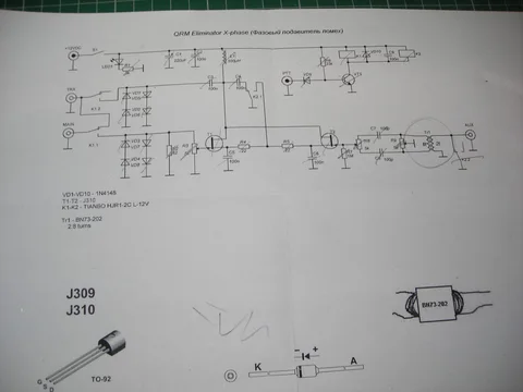
Метод фильтрации паразитных и фазовых шумов для безиндуктивных систем ФАПЧ с дробным коэффициентом деления и синхронизацией с инжектированием от -40,5 до -57 дБ, а интегральный джиттер от 3,57 до 1,48 пс при занимаемой площади 0,6 мм2 и потреблении 190,8 мВт от источника питания 0,85 В.
Полностью цифровой синтезатор частот мощностью 7,1 мВт, 10 ГГц с динамически реконфигурируемым цифровым петлевым фильтром, выполненным по технологии 90 нм CMOS
Для работы на высоких скоростях предлагается фазовый аккумулятор с компенсацией перекоса, который сохраняет преимущества малой рассеиваемой мощности и устраняет накопление проблема перекоса времени.
A 1 ГГц ADPLL с ВЦП субэкспоненты с минимальным разрешением 1,25 пс в КМОП размером 0,18 мкм
Полностью цифровая ФАПЧ для проводных приложений разработана с ВЦП субэкспоненты, которая адаптивно масштабирует свое разрешение в соответствии с разница во времени на входе, а схема самокалибровки на основе реплик применяется к усилителю времени для улучшения линейности в широком диапазоне входных сигналов.
Шумовой фильтр — трехфазный, низкопрофильный | МИСУМИ
- МИСУМИ Главная>
- Электрика и управление>
- Источники питания>
- Шумоподавляющие фильтры и устройства защиты от перенапряжения>
- Шумовые фильтры >
- Шумоподавляющий фильтр — трехфазный, низкопрофильный
Нажмите на это изображение, чтобы увеличить его.
Наведите указатель мыши на изображение для увеличения
- Цена снижена
MISUMI
MISUMI
Противодействие проникновению шума в трехфазную линию электропередач
- Соответствует требованиям UL
● Невыпадающий винт и открывающаяся/закрывающаяся крышка модели улучшают удобство работы
● Модели для установки на DIN-рейку также входят в линейку
∙ Фильтр помех нельзя использовать между инвертором общего назначения и двигателем.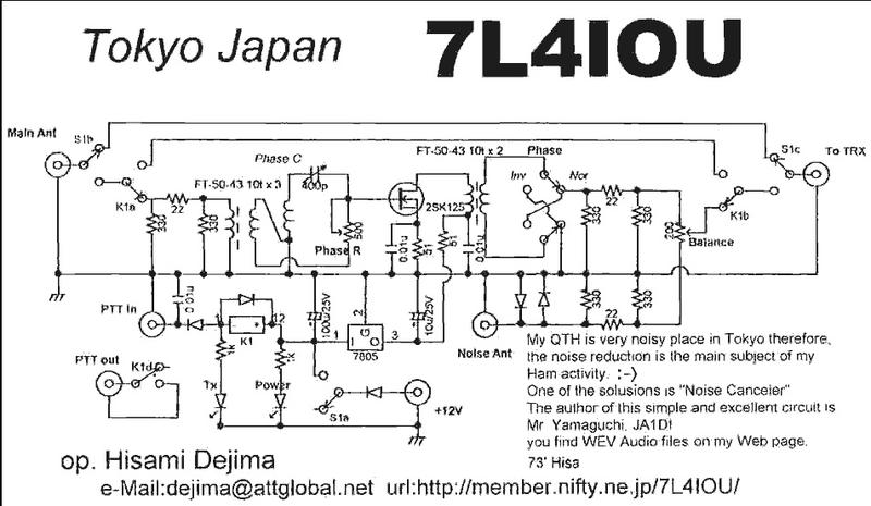
∙ При выборе прерывателей утечки выберите ток утечки фильтра, обращая внимание на шум.
Технические характеристики
| ENF-RTEN-5006 | 3-фазный | 6А | Стандарт (прямой монтаж) |
| ENF-RTEN-5006D | Монтаж на DIN-рейку | ||
| ENF-RTEN-5010 | 10А | Стандарт (прямой монтаж) | |
| ENF-RTEN-5010D | Монтаж на DIN-рейку | ||
| ENF-RTEN-5020 | 20А | Стандарт (прямой монтаж) | |
| ENF-RTEN-5020D | Монтаж на DIN-рейку | ||
| ENF-RTEN-5030 | 30А | Стандарт (прямой монтаж) | |
| ENF-RTEN-5030D | Монтаж на DIN-рейку | ||
| ENF-RTEN-5050 | 50А | Стандарт (прямой монтаж) |
Дополнительная информация
Технические характеристики
| ENF-RTEN-5006 | ENF-RTEN-5010 | ENF-RTEN-5020 | ENF-RTEN-5030 | ENF-RTEN-5050 |
| ЕНФ-РТЕН-5006D | ЕНФ-РТЕН-5010D | ENF-RTEN-5020D | ENF-RTEN-5030D | — |
| РТЭН-5006 | РТЭН-5010 | РТЭН-5020 | РТЭН-5030 | РТЭН-5050 |
| РТЭН-5006D | РТЭН-5010D | РТЭН-5020D | РТЭН-5030D | — |
| 3-фазный | ||||
| 500 В | ||||
| 6А | 10А | 20А | 30А | 50А |
| 2500 В переменного тока / 1-минутный интервал при 20 °C и относительной влажности 65 %: между линией и землей | ||||
100 МОм мин.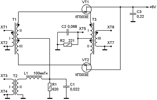 500 В постоянного тока при 20°C, относительной влажности 65 %: между линией и землей 500 В постоянного тока при 20°C, относительной влажности 65 %: между линией и землей |
||||
| 2,5 мА макс. (250 В) / 5,0 мА макс. (500 В) | ||||
| 145 мОм макс. | 60 мОм макс. | 25 мОм макс. | 13 мОм макс. | 7 мОм макс. |
| 0,2 ~ 10 МГц | 0,3 ~ 8 МГц | 0,5 ~ 8 МГц | 0,3 ~ 7 МГц | 0,5 ~ 7 МГц |
| 0,2 ~ 30 МГц | 0,2 ~ 30 МГц | 0,2 ~ 30 МГц | 0,2 ~ 30 МГц | 0,2 ~ 30 МГц |
| Температура: -25 ~ +85 °C, относительная влажность 15 ~ 85 % (без конденсата) | ||||
| UL1283, EN60939 | ||||
| 360 г | 360 г | 560 г | 560 г | 1100 г |
| 400 г | 400 г | 620 г | 620 г | — |
| Part Number |
|---|
| ENF-RTEN-5006 |
| ENF-RTEN-5006D |
| ENF-RTEN-5010 |
| ENF-RTEN-5010D |
| ENF-RTEN-5020 |
| ENF-RTEN-5020D |
| ENF-RTEN-5030 |
| ENF-RTEN-5030D |
| ENF-RTEN- 5050 |
| Номер детали | Скидка за объем | Дней до отгрузки | Номинальный ток (A) Высота | 6 0 Ширина (мм) | Глубина (мм) | ||
|---|---|---|---|---|---|---|---|
| 4 дня | 6 | На винтах | 63 | 120 | 42 | ||
| 6 | DIN-рейка | 63 | 127 | 50,4 | |||
| 4 дня | 10 | На винтах | 63 | 120 | 42 | ||
| 4 дня | 10 | DIN-рейка | 63 | 127 | 50,4 | ||
| 4 дня | 20 | На винтах | 70 | 140 | 42 | ||
| 4 дня | 20 | DIN-рейка | 70 | 140 | 50,4 | ||
| 4 дня | 30 | С винтовым креплением | 70 | 140 | 42 | ||
| Тот же день | 30 | DIN-рейка | 70 | 140 | 50,4 | ||
| Тот же день Stock | 50 | Screw-fastened | 90 | 170 | 54 |
Loading.
